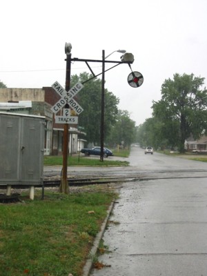
September 20, 2002 -
Sullivan Indiana.
Photo courtesy of
Larry E. Gilbert.
 Wig-Wag, LLC
N-Scale
for the Discriminating Modeler!
|
No E-Bay Auctions at this time |
| Refer
a Friend Please |
|
||||||||||||


| . | Badger |
Bev-Bel |
||||||
Cal Freight |
||||||||
. |
CTT
|
|||||||
Excel
Hobby Tools |
Floquil |
|||||||
Herpa |
||||||||
J-n-J |
||||||||
Kibri |
||||||||
Mini-Figs |
Model
Rail Stuff |
|||||||
| Stewart Products | ||||||||
Tichy
Train Group |
Unreal
Details |
|||||||
| . |
||||||||
Not
all of the items on this page may still be in stock or available
but the information is provided for reference purposes. |
||||||||
(We reserve the right to correct errors and change prices
without prior notice.) |
||||||||